Previous: Day 2 – Raspberry Pi
The Gertboard bottom socket goes into Raspberry GPIO headers. Please upload a test programs into its ATMega pins. There are a lot of tutorials about this, or you can also refer to Gertboard User Manual.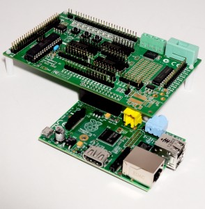
Go to Gertboard ATMega Pin Setup for a proper wiring setup to enable Arduino cababilities in your Gertboard. Wire them as follows.
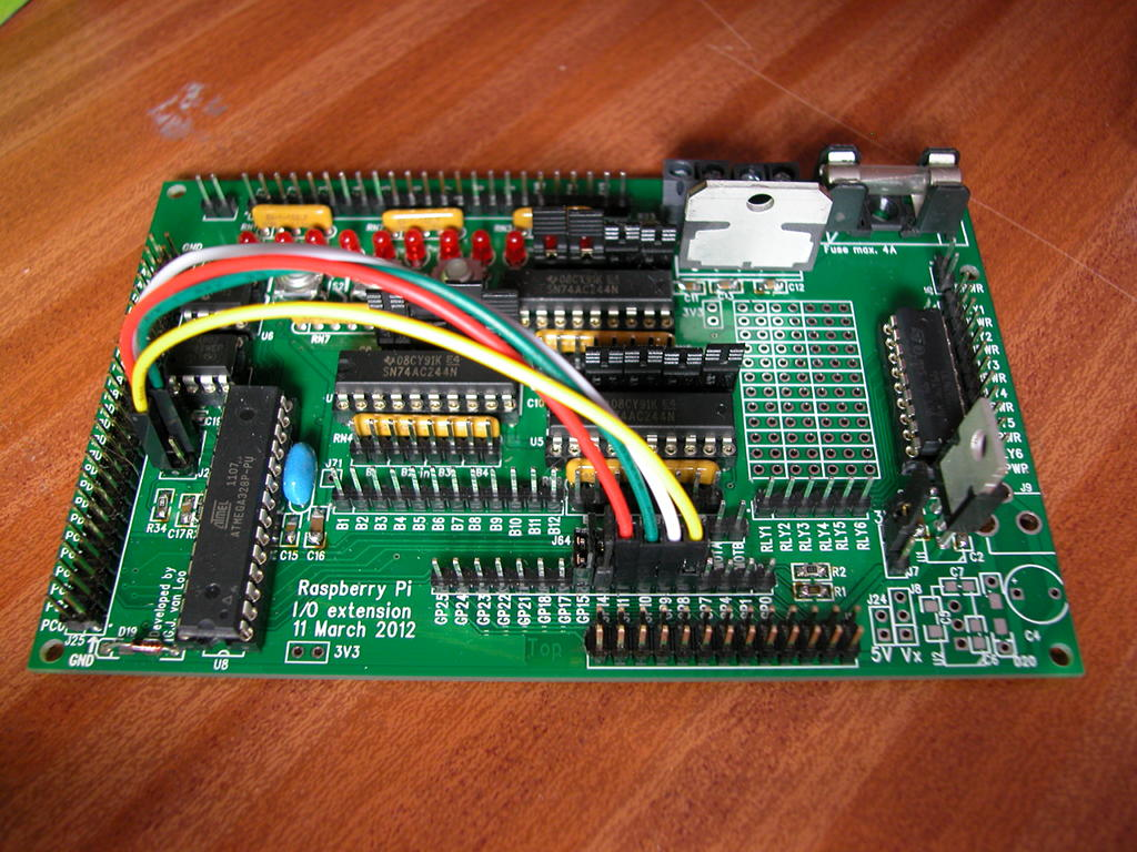
Source: https://projects.drogon.net/raspberry-pi/gertboard
Once everything is ready to go, you need additional wires to connect the Gertboard with your Dagu motor controller.
You need to hook up 4 PWM pins of the Arduino (GertBoard) with motor channels on Dagu 4-channel motorl controller board to control the speeds, so connect them as follows:
- Pin 3 to Motor 1 Speed
- Pin 5 to Motor 2 Speed
- Pin 6 to Motor 3 Speed
- Pin 9 to Motor 3 Speed
Then, you need the normal digital pins of the Arduino to control the direction, so connect them like this:
- Pin 2 to Motor 1 Dir
- Pin 4 to Motor 2 Dir
- Pin 7 to Motor 3 Dir
- Pin 8 to Motor 4 Dir
You do not need to connect the Motor Cur pins with anything, however you need to connect the Ground Pins of the Motor channels to each of the corresponding Arduino ground pin.
Later on we will at servos and sensors using Gertboard buffers, so you need the reserve the other unused pins.
We can now focus on connecting up the DC motors into the motrol controller.
Next: Day 4 – Motor Controller

 with Python 3, OpenCV 3, Pi Camera, and Raspberry Pi 2")
