Arduino Servo library Servo.h despite its simplicity often creates timer conflicts with other PWM pins. In our lab experiment, we found that when we attach servo on Pin 11, PWM capability on at least one of the other pins gets disabled, e.g. the right wheel of the rover attached to Pin 3 becomes a dumb yes/no pin without a speed control. Arduino ATMega328 you can only run 4 PWM connections simultaneously and in a 4WD rover scenario all the available PWM pins have been used by the wheel motors. The only feasible way out is to manually create a PWM function that does not share timer with other pins.
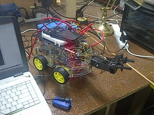
This Arduino sketch demonstrates servo angle positioning with manual pulse width modulation without Arduino IDE servo library. This rotates servo back and forth in tilting / sweeping motion if you attach a robot arm, flag or anything like that. A very useful addition to your rovers or robots.
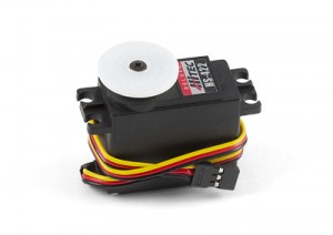
This works very well with Hitek HS-422 servo. Other servos may require slight modifications. Tested on Raspberry Pi with a Gertboard, with servo control pin (yellow wire) attached to Gertboard PB2 pin (Arduino Pin # 10 equivalent) via buffer, and powered with 5V external source through a voltage-shifted RC NiMH battery.
Here is how you hook them up:
- Set up your Gertboard ATMega wiring. Refer to Gertboard manual.
- Link yellow wire of the servo to Gertboard Buffer 2.
- Link red wire to external power source (5 volts battery).
- Link black wire to battery’s ground.
- Link Gertboard PB2 and B2 pins input.
- Place a jumper on B2 output, this will enable the Buffer signal on Buffer 2.
- Upload the following sckectch to Gertboard ATMega.
// Manual servo control - PWM Sweeping
// Copyright 2012 by Zipwhip.
// Modified July 2013 by LinuxCircle.com team
// You are free to use and modify this code in your own software.
// Please give us credit to by mentioning LinuxCircle.com
// in the header of your published code.

#define SERVO_PIN         10  // Any pin on the Arduino or Gertboard will work.

void setup()
{
  pinMode(SERVO_PIN, OUTPUT);

}

int lenMicroSecondsOfPeriod = 25 * 1000; // 25 milliseconds (ms)
int lenMicroSecondsOfPulse = 1 * 1000; // 1 ms is 0 degrees
int first = 0.7 * 1000; //0.5ms is 0 degrees in HS-422 servo
int end = 3.7 * 1000;
int increment = 0.01 * 1000;

void loop()
{
    int current = 0;
    for(current = first; current <end; current+=increment){
         // Servos work by sending a 25 ms pulse.
         // 0.7 ms at the start of the pulse will turn the servo to the 0 degree position
         // 2.2 ms at the start of the pulse will turn the servo to the 90 degree position
         // 3.7 ms at the start of the pulse will turn the servo to the 180 degree position
         // Turn voltage high to start the period and pulse
         digitalWrite(SERVO_PIN, HIGH);

         // Delay for the length of the pulse
         delayMicroseconds(current);

         // Turn the voltage low for the remainder of the pulse
         digitalWrite(SERVO_PIN, LOW);

         // Delay this loop for the remainder of the period so we don't
         // send the next signal too soon or too late
         delayMicroseconds(lenMicroSecondsOfPeriod - current);
    }
    for(current = end; current >first; current-=increment){
         // Servos work by sending a 20 ms pulse.
         // 0.7 ms at the start of the pulse will turn the servo to the 0 degree position
         // 2.2 ms at the start of the pulse will turn the servo to the 90 degree position
         // 3.7 ms at the start of the pulse will turn the servo to the 180 degree position
         // Turn voltage high to start the period and pulse
         digitalWrite(SERVO_PIN, HIGH);

         // Delay for the length of the pulse
         delayMicroseconds(current);

         // Turn the voltage low for the remainder of the pulse
         digitalWrite(SERVO_PIN, LOW);

         // Delay this loop for the remainder of the period so we don't
         // send the next signal too soon or too late
         delayMicroseconds(lenMicroSecondsOfPeriod - current);
    }

}
Original source code that we borrowed from: http://blog.zipwhip.com/2012/03/28/manual-control-of-a-servo-on-the-arduino-for-the-zipwhip-textspresso-machine/
5 thoughts on “Servo Manual Control Without Arduino Servo Library on Raspberry Pi and Gertboard”
Comments are closed.
")


hi, what robot arm did you used?
Hi Fawei,
I tried the first claw Robot Gripper Kit
http://www.dfrobot.com/index.php?route=product/product&manufacturer_id=16&product_id=731
before changing it to Robotic Claw MKII because of weight-lifting capability
https://www.sparkfun.com/products/11524
your two loop comments are inconsistent- the first says 25ms pulse, the second says 20ms pulse.
You can either use 20 or 25 ms. 25ms tend to move the servo smoother. Try each one and let me know how you go.
oh, great tip… worked perfectly…