Some notes on how to charge the batery pack without opening the chassis. The Chassis came with wires. Cut them up and make sure they are enough for everything.
4 Things to be wired up:
- Battery Pack of 5 rechargable batteries (2 wires: positive red , negative black)
- Switch (3 pins: left, middle, right pins)
- Charger Port (3 pins: 2 positive pins + 1 negative pin)
- Romeo (2 wires: positive red, negative black)
Wiring setup
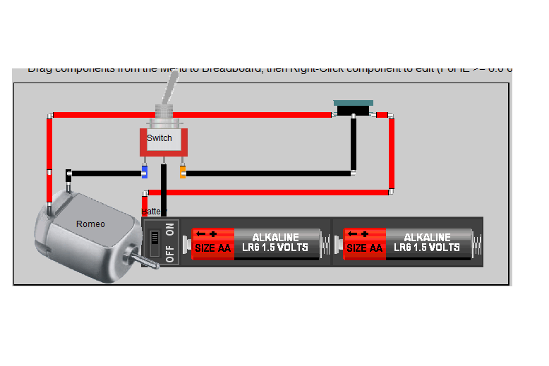
- Connect left Switch pin to Romeo (-) with black cable.
- Connect middle Switch pin to Battery (-) with black cable .
- Connect right Switch pin to Charger pin (-) with black cable.
- Connect Charger first (+) pin to Romeo (+) with red cable.
- Connect Charger second (+) pin to Battery (+) with red cable.
Switch Toggle
Now when we toggle the switch to the right, it will connect left and middle pins, which will power up the Romeo with the battery pack.
When the toggle moved to the left, it will change it to charging mode by connecting up the middle and the left pins, which means the battery is connected to the charger port. You can use any 5v wall charger to infuse the battery.
Some optional connection is:
- Place a short jumper between Switch left and right pins to connect both Romeo and the Battery to the Charger. This will both power up Romeo and charge the battery at the same time.
Once you get the wiring done, let’s build the Internet Rover Robot: https://www.linuxcircle.com/2013/02/28/raspberry-internet-rover-part-1-robotics/
(Visited 890 times, 1 visits today)
")

