After trying different configurations and spent almost 1 month, we finally got the final product!
It’s called Rasinro = Raspberry Internet Rover, sounds a bit Japanese right?
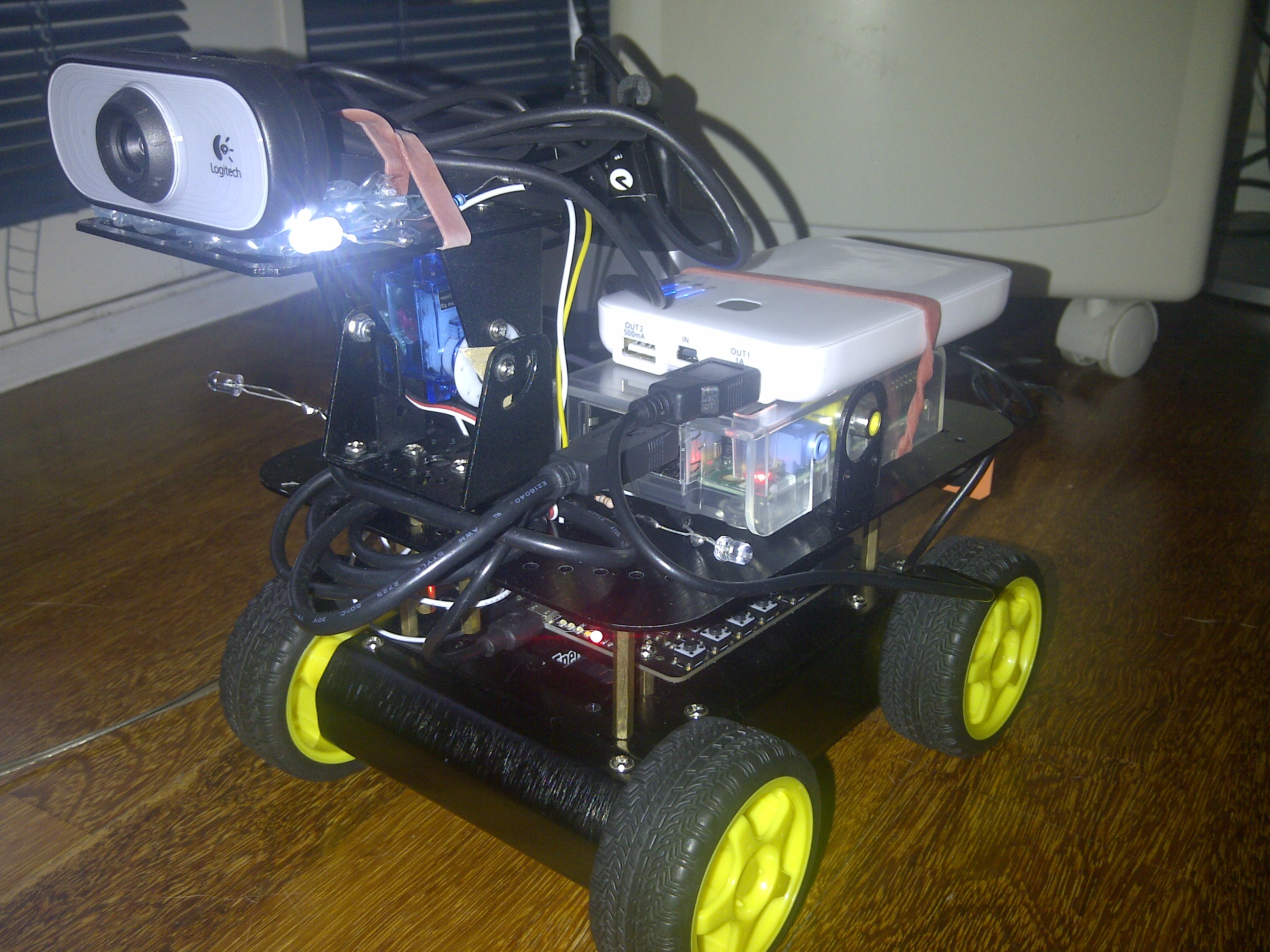
What we need:
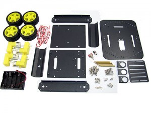
- The 4WD rover chassis: 4 dc motors, wheels, decent platform and casing, and pack of 5 batteries.
- Arduino Device: DFRobot Romeo
- The camera: 1 webcam, 1 tilt and pan servo and bracket
- Raspberry Pi with SD card
- Battery: 5v 2Amp
- USB 4 ports or more
- Several USB cables
Additional / Advance Components:
- 4 leds and transistors for lighting
- Ultrasonic Distance Sensor
Robotics Concept
Most DC motors can rotate both ways. A motor can accept 2 commands: Speed and Direction. Speed is done through Pulse Width Modulation, which means in every cycle (could be a micro second) the signal is being transmitted to the motors voltage port. In Arduino world, the PWM can only take value of 0-254.
We need 2 types of connections to each motor: Digital and Analog. Digital signal is for determining the direction. High means rotate right, Low means rotate left. Analog signal is for setting up the speed i.e. the number of rotation per a given time.
If your motor controller is connected to pin 7 for speed and 8 for direction, this is what the command should look like in Arduino script:
analogWrite (7,a);
digitalWrite(8,HIGH);
Hardware
The 4WD Chassis comes with various components. Please assemble it according to the instruction that came with it, and follow our wiring tutorial to set up the power cable wiring, so you don’t have to open the chassis to wire it.
The motor controller that was used in this test was DFRobot Romeo which has 2 motor ports and several servo pins, was able to be controlled via a microUSB port.
- If you have 4 motors and only have 2 motor ports, connect both left front motor and right front motor to their respective signal (negative and positive) into Motor Port 1. Connect both left and rightrear motors to Motor Port 2.
- Connect your Rasperry Pi with Romeo via USB port
- Power up your Raspberry with a 5v battery pack. This will power Romeo board as well.
Software
You need to configure the rover and arduino device, make sure it works. Please use the following complete code to test it.
#include <Servo.h>
Servo myservo; // create servo object to control a servo
// a maximum of eight servo objects can be created
int pos = 90; // variable to store the servo position
int turn_on =0;
char msgs[5][15] = {
“Up Key OK “,
“Left Key OK “,
“Down Key OK “,
“Right Key OK “,
“Select Key OK” };
char start_msg[15] = {
“Start loop “};
int adc_key_val[5] ={
30, 150, 360, 535, 760 };
int NUM_KEYS = 5;
int adc_key_in;
int key=-1;
int oldkey=-1;
//Standard PWM DC control
int E1 = 5; //M1 Speed Control
int E2 = 6; //M2 Speed Control
int M1 = 4; //M1 Direction Control
int M2 = 7; //M1 Direction Control
///For previous Romeo, please use these pins.
//int E1 = 6; //M1 Speed Control
//int E2 = 9; //M2 Speed Control
//int M1 = 7; //M1 Direction Control
//int M2 = 8; //M1 Direction Control
int led1 = 8;
int led2 = 9;
int led3 = 10;
int led4 = 11;
void light1(int on){
//digitalWrite(13, HIGH);
//delay(20);
if(on==0){
digitalWrite(led1, LOW);
Serial.println(“led 1 off”);
}else{
digitalWrite(led1, HIGH);
Serial.println(“led 1 on”);
}
//digitalWrite(13, LOW);
}
void light2(int on){
//digitalWrite(13, HIGH);
//delay(20);
if(on==0){
digitalWrite(led2, LOW);
Serial.println(“led 2 off”);
}else{
digitalWrite(led2, HIGH);
Serial.println(“led 2 on”);
}
//digitalWrite(13, LOW);
}
void light3(int on){
//digitalWrite(13, HIGH);
delay(20);
if(on==0){
digitalWrite(led3, LOW);
Serial.println(“led 3 off”);
}else{
digitalWrite(led3, HIGH);
Serial.println(“led 3 on”);
}
//digitalWrite(13, LOW);
}
void light4(int on){
//digitalWrite(13, HIGH);
delay(20);
if(on==0){
digitalWrite(led4, LOW);
Serial.println(“led 4 off”);
}else{
digitalWrite(led4, HIGH);
Serial.println(“led 4 on”);
}
//digitalWrite(13, LOW);
}
void stop(void) //Stop
{
digitalWrite(E1,LOW);
digitalWrite(E2,LOW);
digitalWrite(13, HIGH);
delay(10);
digitalWrite(13, LOW);
}
void advance(char a,char b) //Move forward
{
analogWrite (E1,a); //PWM Speed Control
digitalWrite(M1,HIGH);
analogWrite (E2,b);
digitalWrite(M2,HIGH);
}
void back_off (char a,char b) //Move backward
{
analogWrite (E1,a);
digitalWrite(M1,LOW);
analogWrite (E2,b);
digitalWrite(M2,LOW);
}
void turn_L (char a,char b) //Turn Left
{
analogWrite (E1,a);
digitalWrite(M1,LOW);
analogWrite (E2,b);
digitalWrite(M2,HIGH);
}
void turn_R (char a,char b) //Turn Right
{
analogWrite (E1,a);
digitalWrite(M1,HIGH);
analogWrite (E2,b);
digitalWrite(M2,LOW);
}
void turn_FL (char a,char b) //Forward Left
{
analogWrite (E1,a);
digitalWrite(M1,HIGH);
analogWrite (E2,b);
digitalWrite(M2,HIGH);
}
void turn_FR (char a,char b) //Forward Right
{
analogWrite (E1,a);
digitalWrite(M1,HIGH);
analogWrite (E2,b);
digitalWrite(M2,HIGH);
}
void turn_RL (char a,char b) //Forward Left
{
analogWrite (E1,a);
digitalWrite(M1,LOW);
analogWrite (E2,b);
digitalWrite(M2,LOW);
}
void turn_RR (char a,char b) //Forward Right
{
analogWrite (E1,a);
digitalWrite(M1,LOW);
analogWrite (E2,b);
digitalWrite(M2,LOW);
}
void setup(void)
{
int i;
pinMode(13, OUTPUT); //we’ll use the debug LED to output a heartbeat
for(i=4;i<=7;i++)
pinMode(i, OUTPUT);
Serial.begin(19200); //Set Baud Rate
Serial.println(“Run keyboard control”);
myservo.attach(A1);
myservo.write(120);
for (int k = 8; k <= 11; k++){
pinMode(k, OUTPUT);
Serial.println(“Light %sk is ready!”);
}
//test all lights
for (int l = 8; l <= 11; l++)
{
delay(1000);
digitalWrite(l,HIGH);
}
//test off all lights
for (int l = 11; l >= 8; l–)
{
delay(1000);
digitalWrite(l,LOW);
}
//blink 3 times
delay(1000);
for(int loo = 0;loo<3;loo++){
for (int l = 11; l >= 8; l–)
{
digitalWrite(l,HIGH);
}
digitalWrite(13,HIGH);
delay(500);
for (int l = 11; l >= 8; l–)
{
digitalWrite(l,LOW);
}
digitalWrite(13,LOW);
delay(500);
}
}
void loop()
{
adc_key_in = analogRead(A0); // read the value from the sensor
/* get the key */
key = get_key(adc_key_in); // convert into key press
if (key != oldkey) { // if keypress is detected
delay(50); // wait for debounce time
adc_key_in = analogRead(A0); // read the value from the sensor
key = get_key(adc_key_in); // convert into key press
if (key != oldkey) {
oldkey = key;
if (key >=0){
Serial.println(adc_key_in, DEC);
Serial.println(msgs[key]);
Serial.println(key);
}
}
int val2 =key;
if(val2 != -1)
{
switch(val2)
{
case 0://Move Forward
advance (200,200); //move forward in half speed
break;
case 2://Move Backward
back_off (175,175); //move back in a bit slower
break;
case 1://Turn Left
turn_L (255,255);
break;
case 3://Turn Right
turn_R (255,255);
break;
case 4:
stop();
break;
}
}
else stop();
}
if(Serial.available()){
char val = Serial.read();
if(val != -1)
{
switch(val)
{
case ‘w’://Move Forward
advance (200,200); //move forward in half (max speed 255)
Serial.println(“Forward”);
break;
case ‘x’://Move Backward
back_off (175,175); //move back in slow spee
Serial.println(“Reverse”);
break;
case ‘a’://Turn Left
turn_L (255,255);
Serial.println(“Left”);
break;
case ‘d’://Turn Right
turn_R (255,255);
Serial.println(“Right”);
break;
case ‘q’://Turn Left
turn_FL (90,255);
Serial.println(“Forward Left”);
break;
case ‘e’://Turn Right
turn_FR (255,90);
Serial.println(“Forward Right”);
break;
case ‘z’://Turn Left
turn_RL (90,255);
Serial.println(“Reverse Left”);
/*
digitalWrite(13, HIGH);
delay(100);
digitalWrite(13, LOW);
*/
break;
case ‘c’://Turn Right
turn_RR (255,90);
Serial.println(“Reverse Right”);
/*
digitalWrite(13, HIGH);
delay(100);
digitalWrite(13, LOW);
*/
break;
case ‘h’:
Serial.println(“Hello”);
break;
case ‘s’:
stop();
Serial.println(“Stop!”);
break;
case ‘1’:
turn_on=0;
myservo.write(150);
//myservo.write(0);
/*
for(pos = 0; pos < 180; pos += 1) // goes from 0 degrees to 180 degrees
{
// in steps of 1 degree
myservo.write(pos); // tell servo to go to position in variable ‘pos’
delay(15); // waits 15ms for the servo to reach the position
}
for(pos = 180; pos>=1; pos-=1) // goes from 180 degrees to 0 degrees
{
myservo.write(pos); // tell servo to go to position in variable ‘pos’
delay(15); // waits 15ms for the servo to reach the position
} */
break;
case ‘2’:
myservo.write(120);
break;
case ‘3’:
myservo.write(90);
break;
case ‘u’:
light1(1);
light2(1);
break;
case ‘i’:
light3(1);
light4(1);
break;
case ‘o’:
light1(0);
light2(0);
break;
case ‘p’:
light3(0);
light4(0);
break;
}
}
else stop();
}
}
// Convert ADC value to key number
int get_key(unsigned int input)
{
int k;
for (k = 0; k < NUM_KEYS; k++)
{
if (input <= adc_key_val[k])
{
return k;
}
}
if (k >= NUM_KEYS)
k = -1; // No valid key pressed
return k;
}
Make sure you have the LEDS connected to the right pins: 8,9,10,11. Because 4-7 is reserved for the motor control, and pin 13 is for the default pin. Try upload the above codes, and run it off the battery.
Carry on to page 2
[post_view]

 with Python 3, OpenCV 3, Pi Camera, and Raspberry Pi 2")
